


Surface Mounting Technology: Merging with High Voltage Diode Starting from 3KV to 8KV
Unitshine announces the SMTAEZCSP series of high voltage diodes are available from 3,000 to 8,000 volts and custom versions are available in a few other configurations.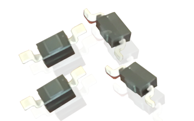
This series of high voltage diode features a unique miniature arrangement that allows for very limited space than typical radial leaded parts. This makes them ideal for applications in air or other conditions with demanding requirements sensitive in dimension.
“We’ve been producing surface mounting technological high voltage product for some time,” said Mr Chong, Technical Product Manager for Unitshine plant. “Our customers have been exceptionally satisfied with the performance of the line we’ve designed, which will be a great benefit to those designing for specialty demands.”
From time to time, Unitshine is about to present high voltage diode that shall cover more volts in this type of package. Full product details can be found on the company’s website, and the parts are in stock and immediately available directly from us to customers throught the world.
Test and Detection of High Voltage Silicon Stack
High voltage silicon stack is composed of multiple high voltage rectifier diodes (silicon particles) in series. When it is tested and detected, the multimeter can be used with the stall of R × 10k to measure its positive and reverse resistance. Normally for high voltage silicon stack, the forward resistance is greater than 200kΩ, and reverse resistance is infinite. If the measured positive and negative have a certain value, then the high-voltage silicon stack could be decided as soft breakdown. 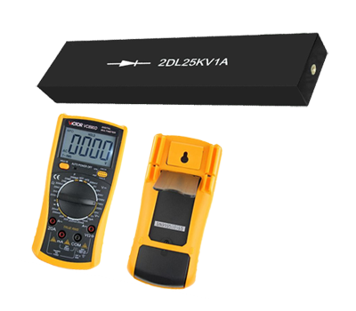
Another method is available. As high voltage silicon stack could functionally be used for rectifying, the multimeter could be switched to DC voltage stall of 250V or 500V, as shown in figure, the high voltage silicon stack is put in series and connected to the 220V AC power supply. Due to the rectifier effect, any deflection of the multimeter pointer will reflect the average current after half wave rectification, therefore the high voltage silicon stack and multimeter make up a half-wave rectifier AC voltmeter.
When the measured high-voltage silicon stack in accordance with the positive connection, the multimeter readings more than 30V is qualified. When connected by reverse connection, the multimeter pointer should reverse the deflection. If the multimeter pointer does not move anyway, it may be that the high voltage silicon stack is internally broken so that the current cannot pass through the multimeter. But it may also be that the high voltage silicon stack has been broken. When short circuit happens, AC voltage can be directly added to the multimeter, but because the AC frequency is 50Hz, the multimeter pointer is too late to swing, so the multimeter with the range switch positioning DC voltage stall shall always read zero.
Therefore, in order to determine short circuit and open circuit for the high-voltage silicon stack, the operator only need position the multimeter's range switch to the stall of AC voltage 250 V or 500 V. If the reading is 220V AC voltage, the measured high voltage silicon stack is decided as short circuit,and if the reading is zero, it shall indicat that the high-voltage silicon stack has been internally broken.
Selection of Heat Sink for Power Modules
Cooling conditions directly affect whether devices can reliably and safely work or not. Different devices and diverse operating conditions require different heat dissipation conditions. At the same time due to size limitation of installation box, and various cooling and ventilation conditions, the choice of heat sinks are not always same. The following paragraph describes how to choose the heat sinks.
The choice of heat sinks should be based on the actual cooling conditions for the devices including load conditions on stable and transient state, ventilation conditions for installing etc. Appropriate consideration of safety factor is necessary, and design shall be made according to the principle that the maximum working temperature of the device shall not be exceeded on steady state.
First, calculate the device's power consumption PAV based on the actual operating current IT (AV) of the device. The formula is as below:
PAV = 0.785VTM * IAV + 0.215VTO * ITAV, or
PAV = VTO * ITAV = 2.47 rT * ITAV
VTM: on-state peak voltage drop;
VTO: device threshold voltage;
rT: device on-state slope resistance.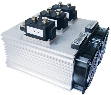
Second, calculate maximum allowable shell temperature for the device based on PAV value.
TC = Tjm - Rjc * PAV
Tjm is the maximum allowable operating junction temperature for the device;
Rthjc is junction thermal resistance for the device.
And then calculate the allowable maximum temperature TS for heat sink surface by the following formula:
TS = TC -Rthcs * Pav
Rthcs is for contact resistance.
Finally, calculate the maximum heat resistance of the heat sink by the following equation:
Rthsa = (Ts-Ta) / PAV
Ta is the ambient temperature.
Based on above, we obtain the value of Rthsa. By referring to heat sink data sheet, we can select heat sink with the same or slightly less value.